Board pro-micro
Detailed Description
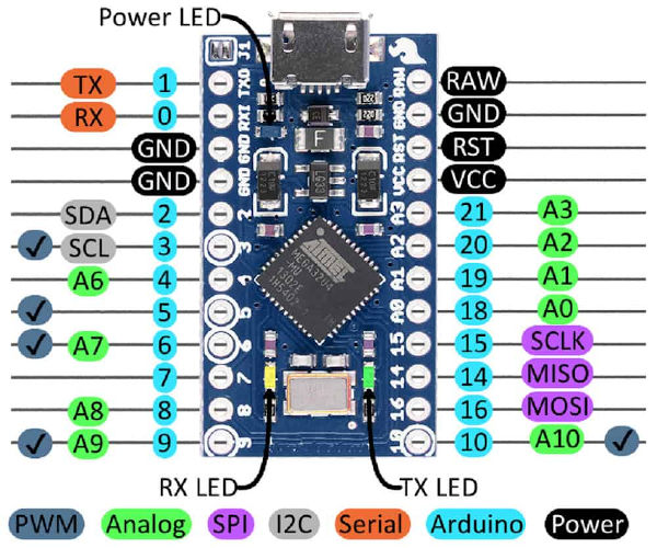
This is an Arduino Leonardo clone board with a MEGA32U4-MI microcontroller that provides the USB interface, and a 16 MHz crystal.
- Pin Configuration
                 TX PD3 0 o  USB  o RAW
                 RX PD2 1 o       o Gnd
                      Gnd o       o RESET
                      Gnd o       o Vcc
                SDA PD1 2 o       o A3 PF4 ADC4 TCK
           OC0B SCL PD0 3 o       o A2 PF5 ADC5 TMS
       ICP1 ADC8 A6 PD4 4 o       o A1 PF6 ADC6 TDO
               OC3A PC6 5 o       o A0 PF7 ADC7 TDI
           ADC10 A7 PD6 6 o       o 15 PB1 SCK
          AIN0 INT6 PE6 7 o       o 14 PB3 MISO PDO
           ADC11 A8 PB4 8 o       o 16 PB2 MOSI PDI
/OC4B OC1A ADC12 A9 PB5 9 o       o 10 PB6 ADC13 OC1B OC4B
- USBASP wiring
 USBASP -> 1  MOSI  <- BOARD
           2  VCC
           4  GND
           5  RST
           7  SCK
           9  MISO
- pro_micro.h
- /* This file is part of the HWA project.* Copyright (c) 2012,2015 Christophe Duparquet.* All rights reserved. Read LICENSE.TXT for details.*//* These are mostly the values as the board is shipped, except the bootsection* size which is 1024 with Diabolo instead of 2048 with the Arduino bootloader.*/#define HW_DEVICE_BOOT bootloader#define HW_DEVICE_BOOTSECTION_SIZE 1024#define HW_DEVICE_CLK_SRC low_power_xosc#define HW_DEVICE_CLK_SRC_HZ 16000000#define HW_DEVICE_CLK_PSC 1#define HW_DEVICE_PIN_HWB disabled#define HW_DEVICE_JTAG disabled//#define HW_DEVICE_STARTUP_DELAYS 16KCK_14CK_64ms//#define HW_DEVICE_BROWNOUT_DETECTION 4100_4500mV//#define HW_DEVICE_SELF_PROGRAMMING enabled#define HW_DEVICE_DEBUG_WIRE disabled#define HW_DEVICE_WATCHDOG_ALWAYS_ON no#define HW_DEVICE_CLOCK_OUTPUT disabled#define HW_DEVICE_FUSE_EBX 0xC/* Settings for building the Diabolo bootloader* Settings for the Diabolo application are in the board's Makefile*/#define DIABOLO_PIN_RX pin_rxd#define DIABOLO_PIN_TX pin_rxd#define DIABOLO_SYNC 5+1#if 0THIS IS NOT DONE YET/* These are mostly the values as the board is shipped, except the bootsection* size which is 1024 with Diabolo instead of 2048 with the Arduino bootloader.*/#define HW_DEVICE_BOOT bootloader#define HW_DEVICE_BOOTSECTION_SIZE 4096#define HW_DEVICE_CLK_SRC low_power_xosc#define HW_DEVICE_CLK_SRC_HZ 16000000#define HW_DEVICE_CLK_PSC 1#define HW_DEVICE_STARTUP_DELAYS 16KCK_14CK_64ms#define HW_DEVICE_BROWNOUT_DETECTION 4100_4500mV#define HW_DEVICE_SELF_PROGRAMMING enabled#define HW_DEVICE_EXTERNAL_RESET enabled#define HW_DEVICE_DEBUG_WIRE disabled#define HW_DEVICE_WATCHDOG_ALWAYS_ON no#define HW_DEVICE_CLOCK_OUTPUT disabled/* Settings for the Diabolo bootloader* BPS and RESET_SIGNAL are only used by `make` to provide* settings to the Diabolo application on the host.*/#define DIABOLO_PIN_RX pin_rxd#define DIABOLO_PIN_TX pin_rxd#define DIABOLO_BPS 230400#define DIABOLO_RESET_SIGNAL DTR#define DIABOLO_CHAR_DELAY 0/* Board pins*/#define ARDUINO#define PIN_D2 (portd,2) // INT0#define PIN_D3 (portd,3) // OC2B INT1#define PIN_D4 (portd,4) // T0#define PIN_D5 (portd,5) // OC0B T1#define PIN_D6 (portd,6) // OC0A AIN0#define PIN_D7 (portd,7) // AIN1#define PIN_D8 (portb,0) // ICP1#define PIN_D9 (portb,1) // OC1A#define PIN_D10 (portb,2) // OC1B SS#define PIN_D11 (portb,3) // OC2A MOSI#define PIN_D12 (portb,4) // MISO#define PIN_D13 (portb,5) // SCK#define PIN_ANALOG_INPUT (pin,adc0)#define PIN_LED _ioa, portb, 1, 5#endif#define ARDUINO#define PIN_LED_GREEN (portd,5)#define PIN_LED_YELLOW (portb,0)#define PIN_LED PIN_LED_YELLOW/* Include HWA definitions*/#include <hwa/atmega32u4_mu.h>
